Get Complete Project Material File(s) Now! »
Implementation
This chapter is allocated to explain how the chose research methods were implemented, what was developed, and how the experimental procedures were planned and conducted.
Application development
The application developed for this research was an Android application. The application was developed using Android Studio [23], which is an integrated development environment (IDE) for development on the Android platform.
Android Studio is a relatively new IDE. It is based on JetBrains IntelliJ IDE, and the first stable version of Android Studio was released in December 2014 [24].
Locantis
The CCIPS that is designed for this thesis has been named Locantis. It is a crossover system between a centralized and a distributed IPS, in which the centralized system has means of distributing its location data. In this case, a NCHAIP system is being used as the platform for collecting location data of the objects being tracked. By distributing the collected location data to a mobile device, providing navigation is a possibility.
The Locantis system is the first NCHAIP system that has means of distribution of location data to a mobile device using Wi-Fi connections. This possibility has not been provided before. Figure 15 is a concept picture of the Locantis system, and shows how different communication types are used. Locantis also provides the possibility to experiment with different combinations of data from the embedded sensors in the android smartphone combined with the location data provided by the NCHAIP system. The embedded sensors that are available in a smart device, and how they can be used together with the location data from the Quuppa system, are covered in a later section: 4.1.2.
As explained above and shown in Figure 15, Locantis is based on a centralised IPS to collect position data and a smart device that acts recipient in a semi-distributed system. Adding more technology and changing the purpose of the system to the one of Locantis creates a new timeline of events. When Locantis is active and running four major events, tag ping, position estimated, request and retrieve position data, are taking place. An example of this can be seen in Figure 16, where the duration of little more than one second is illustrated. The red square marks the events that would be taking place within the duration of one second. Here, the tag is configured to ping its location with 5 Hz and Locantis app is requesting positioning data at 2Hz.
The experimental investigation determines the performance of Locantis by examining how the system is reacting to controlled changes made within the system. In chapter 3.1, the terminology for the experimental investigation is stated and explained. Delta 1 & 2, as can be seen in Figure 16, are under investigation and described in more detail in 4.2.3 and 4.2.3, where the experiments are stated and explained.
Embedded sensors
In chapter 2.5 a number of sensors are listed and two are stated as interesting for this thesis and implementation into Locantis. In this thesis the smartphone running Locantis application is not embedded in any other equipment and is a standalone device. To prove the concept of data combination of the embedded sensor data combined with positioning data, all data is displayed on the smartphones display. In the future, this data would be used as discussed in chapter 2.5.
The geomagnetic sensors application-programming interface (API) is used as a compass to display the heading of exercise participants. The heading and compass data are displayed as shown Figure 17 below. Here it is seen that the current heading is 26° to east-northeast.
The accelerometer data is collected using the accelerometer API. The accelerometer gives values for acceleration forces on the device in relation to X, Y and Z reference planes. The values are represented as numerical values. In Figure 18, below, the acceleration data representation can be seen. These values are from a device that has undergone heavy shaking and then positioned flat on the back on top of a table. The first three rows are the current acceleration forces on the device and the later three rows are maximum-recorded acceleration forces on the device. It should be noted that 0.0 means that there is no change in force on the device. In reality, objects at rest are under the force of 1.0 G in reference to the Z plane.
Communication
In order for the smartphone with the developed application to be able to receive the centrally collected positioning data the application must have some means of communication. Having a smartphone as a platform for simulation equipment has some benefits regarding the communication. Smartphones today have several means of radio communication, such as GSM, 3G, 4G, BT and Wi-Fi, that could be used for this purpose. In this project, Wi-Fi is considered to be the most sufficient and suitable mean of communication for distribution of the positioning data. Wi-Fi requires access points the smartphone can connect to. In this project, the experimental procedure is taking place in a room small enough for only one access point to be required in order to be able to conduct the investigation. Measuring the receiver signal strength indicator (RSSI) value of the single Wi-Fi access point in this investigation ensures that this is the case.
Locantis app receives positioning data by sending HTTP requests to a uniform resource locator (URL) that is unique for the tag that is being tracked. This way of distribution provides posibility to request positioning data from a single tag. There are other ways that the positioning data could be distributed. For instance, user datagram protocol (UDP). This way the NCHAIP system broadcasts the positioning data on a designate internet protocol address (IP address) and the receiving device are listening for broadcasts on that specific IP address. HTTP requests are selected as the way for Locantis app to receive positioning data since the implementation is fairly straight forward and HTTP requests can provide high enough update frequency.
Experimental research
In this chapter the experimental investigation is discussed. The experiments are explained and the different components used are stated.
Experimental set up
The experiments designed for this thesis are conducted in what will be an office landscape, but for now is empty. The testing and experiment area is some 130 2 with concrete walls and roof pillars. The IPS used in the experiments is a NCHAIP system from Quuppa. The system consists of five HAIP locators, a power over Ethernet (POE) switch that connects the HAIP locators and a HAIP controller in a wired network, and 15 HAIP tags included in the demo kit. Figure 19 shows how the different components of HAIP system are connected to each other.
HAIP Locators
HAIP locators are the name of the arrayed antenna elements that are used individually to estimate the location of the tracked objects. Each locators of this NCHAIP system contain nine radio antenna components in an arrayed antenna. The locators are mounted in the ceiling at a tilt elevation angle of 0°.
HAIP Tag setup, configuration and frequency
The frequency on an HAIP tag determines how often the IPS will know the location of the tag, and also decides how much information the IPS has to work with. The NCHAIP system used in these experiments have the possibility to configure the tags to use BLE or regular BT. In these experiments the emphasis is on tags communicating using BLE and the tags are only configured to BLE advertisement on BLE channel 37. The frequency of the tag configured to BLE is in the span of 2Hz to 9Hz. The tags are mounted on a 100x100x600 mm piece of wood. This arrangement is easy to move and gives some elevation from the steel reinforced concrete floor that is believed to cause some distortion.
HAIP controller
HAIP controller is the machine, computer or server, which is running the IPS necessary software’s and it is used to start and stop the IPS. In the demo kit that is being used for this study, the HAIP controller is a Mac mini computer with a Linux-based operating system. Since the Mac mini is a computer and not an unmitigated server, it is connected to keyboard, mouse and screen, which enable real-time monitoring of the tags.
Display Tracking & Monitoring station
Display tracking and monitoring station indicates that real-time monitoring of the tags can be made on external monitoring station that are connected to the HAIP controller.
Figure 20 shows the deployment of the NCHAIP system in the empty office landscaped used during the experiments. In Figure 20, the circular objects represents the HAIP locators and the square objects represents known physical locations that are used as reference points when the true physical location of the locators is triangulated. These reference points are not used for anything else. The red lines indicate the X- and Y-axis of the coordinate system in which the NCHAIP system operates. All measurements and coordinates are in reference to the origin (0.0) of the coordinate system, which is in the cross section of the red lines.
Experimental design
General Hypothesis
The CCIPS is a good replacement system for the established IR-based IPSs that are being used in simulation environments today. The CCIPS can perform within sub-meter accuracy and that latency of the information delivery (distribution) is within the real-time requirements set up for it to be a viable contender as replacement system for the established IPS.
Dependant variable
Precision and accuracy of the location are the dependent variables of these experiments. As explained before, it is important to have both good accuracy and precision in order to be able to rely on the derived location data.
Independent variable In the experiments conducted, the independent variables that are being manipulated are:
• Ping frequency (Ping Frq) of the tag.
• Request rate (RR) of information on the Locantis app.
• Tag movement, either stationary or moving.
• Tag configuration
The tags can be configured as either single tags or combinations of tags. This means that two or more tags are used to estimate an object’s location. The returned location estimates are the combined data of the tags in the combination. This feature is being used in Experiment 3: Estimation accuracy and precision.
Data collection
To be able to determine the suitability of the crossover concept as a suitable replacement system for today’s existing IPSs, some data need to be collected and analysed. This is done by conducting experiments and collecting generated data during the time of the experiments. Data from Experiment 1: Delta time 1 and Experiment 3: Estimation accuracy and precision is collected in log files on the NCHAIP controller. Data from Experiment 2: Delta time 2 is collected from log files generated by the Locantis app. Data from Experiment 2: Delta time 2 is logged by the Locantis app and saved locally on the android phone in order to save time and to avoid having to establish additional connections.
Experiment 1: Delta time 1
The first experiment is to determine how long it takes the NCHAIP system to estimate and calculate the location of the tracked object. This is done to investigate if the location process is fast enough for the system to be viable from a real time perspective. Delta time 1 is calculated by the time difference between the “tags ping” and the instance the NCHAIP has located the origin of that tag.
This experiment is conducted in different configurations, where the tags have different frequencies, and are either stationary or moving. The frequencies selected for this experiment is 2Hz, 5Hz and 9Hz. They are selected to represent slow, medium and high frequency settings in the 2-9Hz-frequency span that is supported BLE frequencies in this NCHAIP system. Figure 21 below shows the different tag configurations for this experiment. All configurations are for single tags if nothing else is stated. “Two-tag combo” indicates that the tag configuration is for a combination of two tags.
The objective is to find out if the different configurations have impact on Delta time 1, which is the time it takes the NCHAIP system to estimate where the tag is. Figure 22, below, shows where in the CCIPS the tag is located. In this experiment the focus is on the tag and the android device running Locantis app is stationary during the experiment. Observations of moving tags are compared to observations of stationary tags in order to test the operational hypothesis.
Operational Hypothesis: Moving and stationary tags have the same Delta time 1, tag configurations with different “ping frequencies” have no impact on Delta time1.
Independent variables: Tag configurations, ping frequencies and if the tags are stationary or moving.
Dependent variables: Delta time 1.
Extraneous variables: Non- equal and non- constant BLE coverage; both are difficult to verify or dismiss.
Experiment 2: Delta time 2
The Locantis app is supposed to be running on an android device carried by the simulation participant who is also carrying the tag. This provides the possibility to distribute the participant’s own location back to him or her. The second experiment is to investigate the time it takes to distribute the location information to the Locantis app from the NCHAIP system. Delta time 2 is the time it takes Locantis app to request and to receive the location information from the NCHAIP system. Figure 23 is an illustration of the code snippets that are used to start and stop the timer function on Locantis app.
This experiment is conducted in different modes, where Locantis app has different request rates (RR) and is either stationary, with stationary tags, or moving together with the tags. The objective is to find out if Delta time 2 increases when the request rate increases. Figure 24, below, shows where the Locantis app is in the CCIPS.
To cover all the previously mentioned modes in this experiment, some experimental groups are formulated. Figure 25 shows the experimental groups that are used in this experiment. The experimental groups have request rate (RR) of 1Hz, 2Hz, or 4Hz. Observations are made when Locantis app and the tags are both stationary and moving. This is to simulate when an exercise participant is stationary and in motion.
At this point, the tag configuration is not important. Since this experiment focuses on the request-response time rather than the actual content of the response, the tag frequency has very little or no impact at al on the experiment.
Experiment 3: Estimation accuracy and precision
The NCHAIP system used to locate and estimate the location of tags being tracked has sub-meter accuracy. This means that the estimation of the tag location is less than a meter away from the real physical tag. Granularity is one of the most important aspects of this investigation, and here the accuracy and precision are being tested. As previously stated, the tags can be configured in several different ways, and one of the possible configurations supports combinations of tags. This means that two or more tags are used to represent a common object. The location data generated from this configuration is seen as a single “tagged object” and it is the combination of all the tags. Both a single tag and the two-tag combination are used in this experiment. As discussed above, the tags are positioned to be clear of any distortion from steel reinforcements in the floor and in the case of the two-tag combo configuration; the tags are positioned centre-to-centre 550 millimetres apart. Two tags are combined as on in this experiment to simulate the effects of two tags positioned on the shoulders of a simulation participant and to investigate if the two-tag combination centre point has the same or even greater accuracy and precision than a single tag.
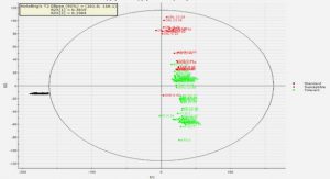
The tag estimates done in this experiment are compared to 14 randomly selected reference points. The reference points are selected at random in the area where the NCHAIP is most likely to have good coverage. The coverage estimation is determined using Quuppa site planner and deployment tools option for rendering coverage estimate. The reference points are marked up on the floor with tape and are measured against the origin (0.0) in the coordinate system where the NCHAIP system is working using laser tape measure. This gives the reference points coordinates with a margin of error of less than 5 mm, which is considered to have insignificant impact on the observations. Figure 26, below, shows these 14 reference points in the area where the experiments are conducted and Figure 27 shows the rendered coverage estimates.
During the experiment, the tag rig is positioned with its centre point on the reference point and the tag rig aligning the Y-axis. The correctness of the aligning along the Y-axis is not critical since it is the centre point compared to the reference point that is interesting. However, to have some consistency during the measures, the rig is aligned against the tape and markings on the floor.
Operational Hypothesis 1: The granularity (accuracy) of the NCHAIP system is within 300 mm of the physical reference points.
Operational Hypothesis 2: The combo-Tag configuration has greater accuracy and precision than the single tag configuration.
Independent variables: Tag configurations, both single tag and combo tag configurations.
Dependent variables: Accuracy and granularity of the tag location.
Extraneous variables: Non- equal and non- constant BLE coverage and distortions in the environment, such as from steel reinforced concrete. This is difficult to dismiss despite countermeasures.
Reliability of measures
Reliability refers to consistency and repeatability of measurable results from methods or instruments [22, p. 128].
Delta 1
Delta 1 is the time it takes the NCHAIP system to estimate the location of the tag. Comparing Linux epoch timestamps created when the tag is pinging its location and when the location is estimated does this calculation. Delta 1 does not include the time it takes the signal to reach the receivers. BLE signals are radio waves and travels close to the speed of light (approx. 300,000,000 meters/second). Since the longest tag-to-locator distance in these experiments are approx. 10 meters, the time it takes the signal to reach the locators is negligible.
Delta 1 is calculated after the experiments are conducted by importing logged data from the experiments into Microsoft Office Excel, and by subtracting the numerical value of the earlier Linux epoch timestamp from the numerical value of the later one. What is left from the subtraction is a delta time measured in milliseconds. Using Microsoft Excel to do the calculations is considered to be reliable; the tool is not going to do calculation errors.
Delta 2
Delta 2 is calculated by setting a timer at the moment the request for location information is sent and by stopping the timer the moment the requested information has reached the Locantis app. The timer is an embedded function in the java language named “SystemNanoTime()” that returns the Linux epoch timestamp in nanoseconds when the call for the function is made. This makes it available and easy to use in android studio development tool. Delta 2 is the difference between the start and stop timestamps. Figure 23 shows how easily the system nano-time function can be used to time operations.
Using this function to calculate Delta 2 is considered to be reliable. It is an embedded function in the java language that cannot be bypassed in any way other that removing the function calls from the source code. Delta 2 is logged in the log file generated by the Locantis app, and for the data analysis to be convenient, this too is imported into Microsoft Excel. The calculation of Delta 2 is considered to be reliable.
Estimation accuracy and precision
Estimation of accuracy and precision is a comparative operation, where positioning data from tags are collected and compared to reference points. To be able to determine the accuracy and precision, the logged data has to be imported into Microsoft Excel in order to be able to present the data as human readable. Here the logged positioning data is compared to manually entered reference points of the physical spots where the measurements have been done. Even thou the tools are reliable, determine what is considered to be high accuracy and precision is very subjective, it has to be done by a human. Someone has to decide if the measured data is accurate or not.
Validity
Validity is important for both physical instruments and experiments. Validity for instruments refers to the instruments capacity and the instrument’s ability to measure what is intended to measure. For experiments, this translates to the accuracy of observations [22, p. 128]. There are several different kinds of validity that needs to be considered.
Internal validity
Internal validity is the degree of confidence that observed results is related to the changes made on independent variables rather than unrelated or unknown factors [22, p. 128].
The internal validity for the experiments conducted is considered to be high. The data collected during the test indicates that the independent variables have an impact on the dependent variables. Thou some extraneous variables have some influence on the tests; the independent variables impact have significant and clear impact on the dependent variable.
External validity
External validity refers to the generalizability of research findings, and the extent to which the findings can be generalized [22, p. 128].
Generally, experiments conducted in closed and laboratory environments tend to have low external validity. It is difficult to generalise the findings enough for them to be valid for anything else than the study that generated them. But this study is conducted in an environment that very well could be a real deployment based on an actual business case. The external validity is considered to be high as the research findings from this study easily could be generalised and translated for other purposes.
Contents
1 Introduction
1.1 BACKGROUND
1.2 PURPOSE AND RESEARCH QUESTIONS
1.3 DELIMITATIONS
1.4 OUTLINE
2 Theoretical background
2.1 TECHNOLOGIES
2.2 POSITIONING TECHNIQUES
2.3 STANDARDS FOR IPS USING BLE
2.4 THE CCIPS
2.5 EMBEDDED SENSORS IN SMARTPHONES
2.6 PRECISION, ACCURACY AND GRANULARITY
2.7 SIMULATIONS
2.8 EXERCISE MODEL
3 Method
3.1 EXPERIMENTAL RESEARCH DESIGNS
3.2 SYSTEM DEVELOPMENT
4 Implementation
4.1 APPLICATION DEVELOPMENT
4.2 EXPERIMENTAL RESEARCH
4.3 RELIABILITY OF MEASURES
4.4 VALIDITY
5 Findings and analysis
5.1 DIFFERENCE BETWEEN CENTRALIZED AND DISTRIBUTED SIMULATION SYSTEMS
5.2 IMPACT ON CURRENT EXERCISE MODELS
5.3 DELTA TIME1
5.4 DELTA TIME 2
5.5 ESTIMATION ACCURACY AND PRECISION
6 Discussion and conclusions
6.1 DISCUSSION OF METHOD
6.2 DISCUSSION OF FINDINGS
6.3 CONCLUSIONS
6.4 FUTURE WORK
References
GET THE COMPLETE PROJECT